MEMS-based heading and attitude measurement system has become a key product in the automotive electronics industry and consumer electronics due to its low cost and simple structure. It is widely used in industrial automation, large medical equipment, intelligent robots, instrumentation, engineering machinery and other fields. It can be applied to electronic consumer products such as game consoles, music players, and digital cameras.
In the MEMS heading and attitude measurement system, FPGA is used as the main processor to form an embedded data acquisition and processing system. The signals of MEMS gyroscope and MEMS accelerometer are collected and digitally filtered, and the real-time attitude of the carrier is calculated according to the attitude calculation algorithm and course.
The heading and attitude measurement system based on MEMS devices is mainly composed of MEMS gyroscope and accelerometer. The micro inertial measurement unit is sensitive to linear acceleration in the three directions of X, Y, and Z. It needs to have three micromechanical accelerometers to sense the angular velocity of rotation around the three directions of X, Y, and Z. It needs to have three micromechanical gyroscopes. That is, a total of six sensors are required to be fixedly connected to the support of the micro inertial measurement unit device.
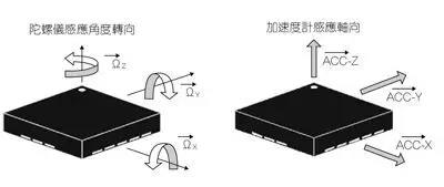
Installed in perpendicular positions. Since the three-degree-of-freedom accelerometer can sense acceleration in three directions, the micro-inertial measurement unit only needs one accelerometer to measure the angular velocity signals along the three axes of the carrier coordinate system. The micromachined accelerometer measures acceleration signals along the three axes of the carrier coordinate system.
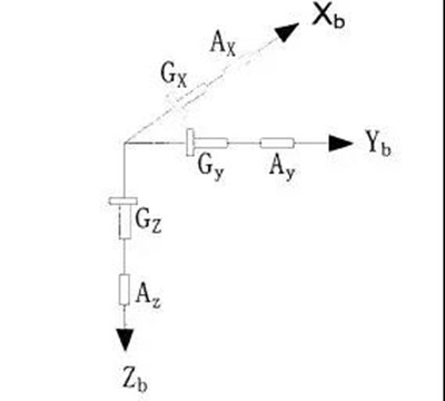
The figure below is the installation structure diagram of the MEMS inertial device measurement unit. Three single-axis MEMS gyroscopes and a three-axis MEMS accelerometer are respectively installed on three orthogonal surfaces of a hexahedron. The X axis and the Y axis are two orthogonal axes, and the Z axis, the X axis, and the Y axis form a right-handed coordinate system, which constitutes the three-dimensional coordinate system of the measuring body.
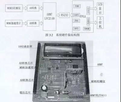
The digital processing system of the heading and attitude measurement system of the MEMS inertial device can process the input of three gyroscope signals, three accelerometer signals and three temperature signals, including data acquisition, 16-bit AD conversion, temperature compensation, and noise reduction filtering , Attitude calculation and other digital algorithm processing, and finally digital output in RS-232 format. The hardware structure and physical diagram of the heading and attitude system are shown in the following figure.
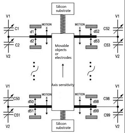
The accelerometer is an electromechanical device, including holes, cavities, springs, and pipes, and the machining uses micromachining technology. The accelerometer uses a multilayer wafer process to measure the acceleration force by detecting the displacement of the object's center of gravity relative to the fixed electrode. The force causes the object to shift, and then the capacitance changes. Connecting multiple electrodes in parallel can obtain a larger capacitance change and make it easier to detect displacement (see the figure below). V1 and V2 are connected to each side of the capacitor, and the center of the capacitor divider is connected to the object.
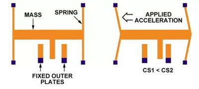
Accelerometers measure linear acceleration (in mV/g) along one or more axes; gyroscopes measure angular velocity (in mV/deg/s). The output of the accelerometer does not respond to changes in angular velocity.

 +86 189 2129 2620
+86 176 0611 8008 sales@bwsensing.com


