At the beginning of the 20th century, the research on the attitude control of quadcopter was not paid much attention. Since the beginning of the 21st century, science and technology have developed rapidly, and research on quadcopters has been continuously carried out. Its functions continue to increase, stability and battery life continue to increase, but its stability is not ideal.
Aiming at the shortcomings of low stability of the quadcopter, a digital signal transmission system is added to enable long-distance two-way communication with the host computer, and then the remote control signal is transmitted to the aircraft, and the attitude of the quadcopter is controlled by the current attitude angle Information such as, altitude, etc. is returned to the host computer, and a two-way data link is established between the host computer and the quadcopter. The quadrocopter will feed back the remote control signal, aircraft attitude and position information to the host computer. After the host computer undergoes a stability test, The above information is then negatively fed back to the quadcopter. Under the condition that the communication speed is 1Kbps, the effective distance can reach more than 3000 meters, so as to achieve long-distance operation.
The four-axis aircraft includes four wings, the size of the four motors is the same, each motor controls a rotor, the flight control computer controls the four motors, and the four motors are connected by a bracket. The specific structure is shown in Figure 1.
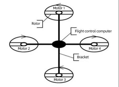
Figure 1 Structure diagram of quadcopter
The four-axis aircraft constitutes the main torso through the brackets of four motors, and the three-dimensional six degrees of freedom are formed by the different movements of the torso, and the corresponding centrifugal force is generated by different acceleration and deceleration of the motors. According to the direction of the centrifugal force to realize the control of the nonlinear degree of freedom, thereby balancing the anti-torque, the attitude control states of the quadcopter are as follows.
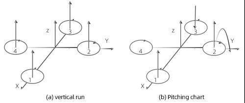
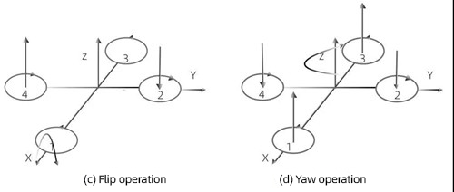
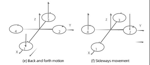
The classic single-loop positional PID algorithm: PID(output)=P*(attitude angle error)+I*(error integral)+D*(error differential), although the self-balancing of the quadcopter can be achieved, but due to The severe lag of the error differential term and the extremely unstable quadrocopter make the actual PID tuning process very long and difficult to succeed. So we make improvements on this algorithm; by controlling two single-loop PID algorithms, that is, cascade PID (output) = inner loop P* (attitude angle error) + inner loop I* (error integral) + inner loop D (Angular velocity) + outer ring P (attitude angle error). The formula adjustments corresponding to the values of P, I, and D of the inner and outer rings have the following parts:
(1) The proportional term inner loop P output: the value of inner loop P affects the stability of the four axes, that is, the value of P is proportional to the system stability error K:

2) The output of the inner loop I of the integral term: Similarly, the value of the inner loop I also affects the stability of the four-axis. Under the integration of the time constant, K and I are proportional:

(3) Differential term inner loop D output: the differential term plays a vital role in adjusting the deviation value. When the deviation value changes, a constant deviation value is added to the P terminal to reduce the stability error. Improve system stability:
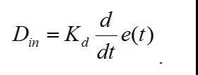
(4) Output of proportional term outer loop P: Similarly, the value of outer loop P also affects the stability of the four-axis. The value of P is proportional to the system stability error K, and the four-axis stability is gradually improved:

In summary, the inner and outer loops P, I, and D get a formula, that is, the mathematical expression of PID control:

For its cascade PID algorithm steps, the specific implementation is shown in Figure 5.

Figure 5 Cascade PID algorithm flow chart
When adjusting the cascade PID through the data in the host computer, set the desired angle, output the desired angle to the angle loop PID controller, and then output to the angular velocity loop PID controller through the angle loop PID, and then use four PWMs The wave is output to the corresponding four motors, and IMU (Inertial Measurement Monitoring) is used to re-measure the stable value of the attitude control of the quadcopter at any time. On the one hand, the IMU is negatively fed back to the angular velocity loop PID controller; on the other hand, the IMU is negatively fed back to the desired angle in a 3D posture, and the previous steps are looped until it is adjusted to a relatively stable balance value. Regarding how to set the cascade PID value, this article mainly adjusts the inner and outer loop P, I, D values in the cascade PID, so that the stability of the four-axis is gradually improved.
By adjusting the P, I, and D values of the inner and outer loops in the cascade PID algorithm, the attitude control stability of the quadcopter is greatly improved, so as to successfully complete the tasks of load detectors and aerial photography. However, in actual operation, there is still a certain gap between theory and practice, and the four-axis will be disturbed by the external environment. Therefore, it is necessary to optimize the software part and upgrade the hardware part, and finally achieve the desired effect slowly.

 +86 189 2129 2620
+86 176 0611 8008 sales@bwsensing.com


